防撞功能
_防撞功能可用于在车辆撞上障碍物之前自动减速和停车。 当使用基于加速度的多旋翼飞行器时,它可以启用 Position mode (or VTOL vehicles in MC mode).
它可以在以下情况下为多旋翼飞行器启用 Position mode, 并且可以使用来自非机载配套计算机、MAVLink上的非机载测距仪、连接到飞行控制器的测距仪或上述任何组合的传感器数据。
如果传感器范围不够大,碰撞预防可能会限制车辆的最高速度! 它还可以防止在没有传感器数据可用的方向上移动(即,如果没有后部传感器数据,您将无法向后飞行)。
TIP
如果高飞行速度至关重要,请考虑在不需要时禁用防撞功能。
TIP
确保您在想要飞行的所有方向上都有传感器/传感器数据(启用防撞功能时)。
综述
车辆限制当前速度,以便在接近障碍物时减速,并调整加速度设定值,以禁止碰撞轨迹。 为了远离(或与之平行的)障碍物,用户必须使无人机/无人车朝向不靠近障碍物的设定点移动。 如果确定在所请求的设定点两侧的固定范围内存在“更好”的设定点,算法将对设定点方向进行微调。
用户通过_QGroundControl_收到通知,而_Collion Prevention_正在主动控制速度设定值。
PX4软件设置将在下一节中介绍。 如果您使用连接到飞行控制器的距离传感器进行防撞,则需要按照中所述进行连接和配置 PX4 Distance Sensor. 如果您使用配套电脑提供障碍物信息,请参阅 [companion setup](#companion
支持的测距仪
Lanbao PSK-CM8JL65-CC5 [Discontinued]
在撰写本文时,PX4允许您使用 Lanbao PSK-CM8JL65-CC5 用于“开箱即用”防撞的红外距离传感器,只需最小的额外配置:
- First attach and configure the sensor, 并且能够防止碰撞(如上所述,使用 CP_DIST).
- 使用设置传感器方向 SENS_CM8JL65_R_0.
LightWare LiDAR SF45 Rotating Lidar
PX4 v1.14 (and later) supports the LightWare LiDAR SF45 旋转激光雷达,提供320度传感。
其他测距仪
其他传感器的使能需要修改驱动代码来设置传感器方向和视觉范围。
- 在特定端口上连接和配置距离传感器 (see sensor-specific docs) 并使用 CP_DIST.
- 修改驱动程序以设置方向。 This should be done by mimicking the
SENS_CM8JL65_R_0parameter (though you might also hard-code the orientation in the sensor module.yaml file to something likesf0x start -d ${SERIAL_DEV} -R 25- where 25 is equivalent toROTATION_DOWNWARD_FACING). - Modify the driver to set the field of view in the distance sensor UORB topic (
distance_sensor_s.h_fov).
PX4 (软件)设置
Configure collision prevention by setting the following parameters in QGroundControl:
| 参数 | 描述 |
|---|---|
| CP_DIST | Set the minimum allowed distance (the closest distance that the vehicle can approach the obstacle). Set negative to disable collision prevention. > Warning This value is the distance to the sensors, not the outside of your vehicle or propellers. Be sure to leave a safe margin! |
| CP_DELAY | Set the sensor and velocity setpoint tracking delay. See Delay Tuning below. |
| CP_GUIDE_ANG | Set the angle (to both sides of the commanded direction) within which the vehicle may deviate if it finds fewer obstacles in that direction. See Guidance Tuning below. |
| CP_GO_NO_DATA | Set to 1 to allow the vehicle to move in directions where there is no sensor coverage (default is 0/False). |
| MPC_POS_MODE | Set to Direct velocity or Smoothed velocity to enable Collision Prevention in Position Mode (default is Acceleration based). |
算法描述
来自所有传感器的数据被融合到车辆周围36个扇区的内部表示中,每个扇区包含传感器数据和上次观察时间的信息,或者表示该扇区没有可用数据。 当车辆被命令向特定方向移动时,会检查该方向半球的所有扇区,以查看移动是否会使车辆更靠近任何障碍物。 如果是这样,无人机的速度就会受到限制。
该速度限制考虑了通过以下方式调整的内部速度环 MPC_XY_P, as well as the jerk-optimal velocity controller via MPC_JERK_MAX and MPC_ACC_HOR. 速度受到限制,车辆将及时停车,以保持中规定的距离 CP_DIST. 每个扇区的传感器范围也被考虑在内,通过相同的机制限制速度。
INFO
如果特定方向上没有传感器数据,则该方向上的速度限制为0(防止车辆撞上看不见的物体)。 如果您希望在没有传感器覆盖的情况下自由移动,可以通过设置来启用 CP_GO_NO_DATA to 1.
车辆跟踪速度设定点和从外部来源接收传感器数据的延迟都是通过以下方式保守估计的 CP_DELAY parameter. This should be tuned 对于特定的车辆。
如果与命令扇区相邻的扇区明显“更好”,则可以将请求输入的方向修改到中指定的角度CP_GUIDE_ANG. 这有助于微调用户输入,以“引导”车辆绕过障碍物,而不是被它们卡住。
范围数据丢失
如果自动驾驶仪在超过0.5秒的时间内没有从任何传感器接收到距离数据,它将输出警告_没有收到距离数据,不允许移动_。 这将迫使xy中的速度设定点为零。 在5秒未收到任何数据后,车辆将切换到 HOLD mode. 如果您希望车辆能够再次移动,则需要通过将参数[CP_DIST](#CP_DIST)设置为负值或切换到其他模式来禁用防撞功能 Position mode (e.g. to Altitude mode or Stabilized mode).
如果您连接了多个传感器,但其中一个失去了连接,您仍然可以在报告传感器的视场(FOV)内飞行。 故障传感器的数据将过期,该传感器覆盖的区域将被视为未覆盖,这意味着您将无法移动到那里。
WARNING
启用时要小心 CP_GO_NO_DATA=1, 这允许车辆在传感器覆盖的区域外飞行。 如果您与多个传感器中的一个失去连接,则故障传感器覆盖的区域也将被视为未覆盖,您将能够不受限制地移动到那里。
CP_DELAY Delay Tuning
有两个主要的延迟源需要考虑:传感器延迟和车辆速度设定点跟踪延迟。 这两个延迟源都使用 CP_DELAY 参数
可以假设直接连接到飞行控制器的距离传感器的_sensor delay_为0。 对于外部视觉系统,传感器延迟可能高达 0.2秒。
车辆速度设定点跟踪延迟可以通过全速飞行来测量 Position mode, then commanding a stop. 然后可以从日志中测量实际速度和速度设置值之间的延迟。 跟踪延迟通常在 0.1 至 0.5秒之间,取决于机身尺寸和调试情况。
TIP
如果车辆速度在接近障碍物时振荡(即减速、加速、减速),则延迟设置得太高。
CP_GUIDE_ANG Guidance Tuning
取决于机身,环境类型和飞行员技能,可能需要不同数量的制导。 Setting the CP_GUIDE_ANG 参数设置为0将禁用导航,导致车辆仅在指令方向上精确移动。 增大此参数将使无人机选择最佳方向来避开障碍物,从而更容易飞过狭窄的间隙,并与物体周围保持最小间距。
如果此参数太小,车辆在靠近障碍物时可能会感到“卡住”,因为只允许以最小距离远离障碍物。 如果参数太大,车辆可能会感觉像是在操作员没有指令的方向上滑离障碍物。 从测试来看,尽管不同的车辆可能有不同的要求,但是 30度是一个很好的平衡点。
INFO
在没有传感器数据的情况下,导航功能永远不会将车辆指向某个方向。 如果车辆感觉只有一个指向前方的距离传感器卡住,这可能是因为导航系统由于缺乏信息而无法安全地调整方向。
算法描述
来自所有传感器的数据被融合到车辆周围72个扇区的内部表示中,每个扇区包含传感器数据和上次观察时间的信息,或者表示该扇区没有可用数据。 当车辆被命令向特定方向移动时,会检查该方向半球的所有扇区,以查看移动是否会使车辆比允许的任何障碍物更靠近. 如果是这样,无人机的速度就会受到限制。
然后,该算法可以分为两部分,即来自操作员的加速度设定点的约束和车辆当前速度的补偿。
INFO
如果在特定方向上没有传感器数据,则该方向的移动将限制为0(防止车辆撞上看不见的物体)。 如果您希望在没有传感器覆盖的情况下自由移动,可以通过设置来启用 CP_GO_NO_DATA to 1.
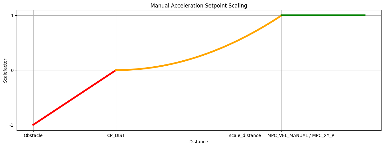
加速约束
为此,我们将加速度设定点分为两个部分,一个平行于离障碍物最近的距离,另一个垂直于障碍物。然后,我们根据下图缩放每个部分。
Velocity compensation
This velocity restriction takes into account the jerk-optimal velocity controller via MPC_JERK_MAX and MPC_ACC_HOR. Whereby The current velocity is compared with the maximum allowed velocity so that we are still able to break based on the maximal allowed jerk, acceleration and delay. from this we are able to use the proportional gain of the acceleration controller(MPC_XY_VEL_P_ACC) to transform it into an acceleration.
Delay
与碰撞预防相关的延迟,无论是在车辆跟踪速度设定点还是从外部来源接收传感器数据方面,都是通过以下方式保守估计的CP_DELAY parameter. This should be tuned 对于特定的车辆。
Companion Setup
WARNING
配套实施/设置目前未经测试(原始配套项目未得到维护,已存档)。
如果使用配套计算机或外部传感器,则需要提供一系列 OBSTACLE_DISTANCE 信息,应反映检测到障碍物的时间和地点。
发送消息_must_的最小速率取决于车辆速度-在较高的速率下,车辆将有更长的时间对检测到的障碍物做出响应。 该系统的初步测试使用了一辆以4 m/s的速度行驶的车辆 OBSTACLE_DISTANCE 以10Hz(视觉系统支持的最大速率)发射消息。 该系统可以在显著更高的速度和更低的频率距离更新下很好地工作。
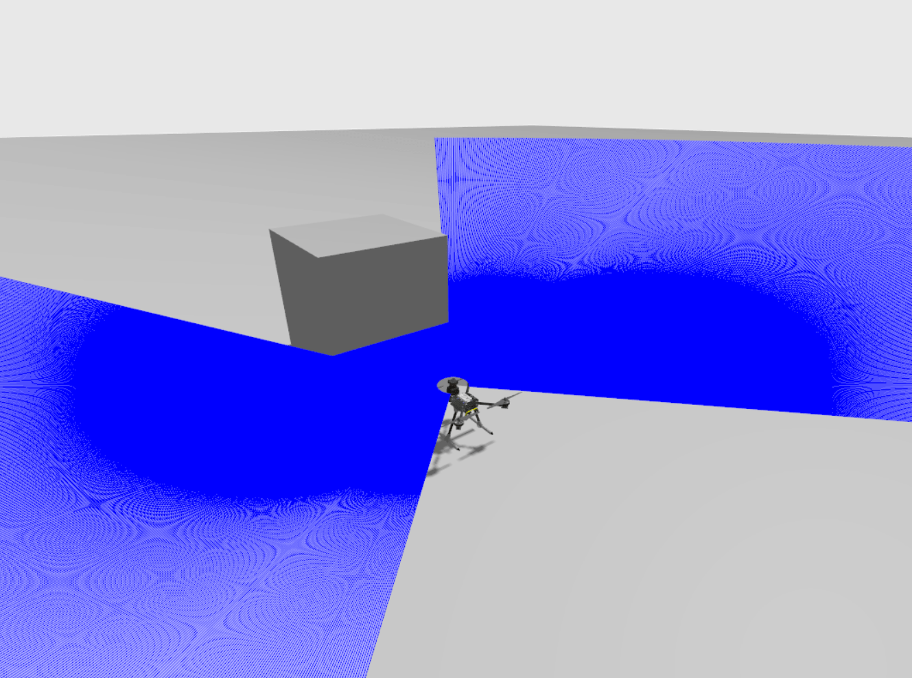
Gazebo Simulation
_碰撞预防_可以使用以下工具进行测试 Gazebo with the x500_lidar_2d model. 为此,请运行以下命令,使用x500激光雷达模型启动模拟:
make px4_sitl gz_x500_lidar_2d接下来,将相关参数调整为适当的值,并在模拟世界中添加任意障碍物,以测试碰撞预防功能。
下图显示了Gazebo中碰撞预防的模拟。
Development Information/Tools
Plotting Obstacle Distance and Minimum Distance in Real-Time with PlotJuggler
PlotJuggler 可用于实时监测和可视化障碍物距离,包括到最近障碍物的最小距离。
要使用此功能,您需要向PlotJuggler添加一个响应式Lua脚本,并配置PX4导出 obstacle_distance_fused UORB topic data. Lua脚本通过提取 obstacle_distance_fused 每个时间步的数据,将距离值转换为笛卡尔坐标,并将其推送到PlotJuggler。
步骤如下:
Follow the instructions in Plotting uORB Topic Data in Real Time using PlotJuggler
配置PX4以发布障碍物距离数据(以便PlotJuggler可以使用):
Add the
obstacle_distance_fusedUORB topic to yourdds_topics.yamlso that it is published by PX4:sh- topic: /fmu/out/obstacle_distance_fused type: px4_msgs::msg::ObstacleDistanceFor more information see DDS Topics YAML in uXRCE-DDS (PX4-ROS 2/DDS Bridge).
打开PlotJuggler并导航到 Tools > Reactive Script Editor section. In the Script Editor 选项卡中,在相应的部分中添加以下脚本:
Global code, executed once:
luaobs_dist_fused_xy = ScatterXY.new("obstacle_distance_fused_xy") obs_dist_min = Timeseries.new("obstacle_distance_minimum")function(tracker_time)
luaobs_dist_fused_xy:clear() i = 0 angle_offset = TimeseriesView.find("/fmu/out/obstacle_distance_fused/angle_offset") increment = TimeseriesView.find("/fmu/out/obstacle_distance_fused/increment") min_dist = 65535 -- Cache increment and angle_offset values at tracker_time to avoid repeated calls local angle_offset_value = angle_offset:atTime(tracker_time) local increment_value = increment:atTime(tracker_time) if increment_value == nil or increment_value <= 0 then print("Invalid increment value: " .. tostring(increment_value)) return end local max_steps = math.floor(360 / increment_value) while i < max_steps do local str = string.format("/fmu/out/obstacle_distance_fused/distances[%d]", i) local distance = TimeseriesView.find(str) if distance == nil then print("No distance data for: " .. str) break end local dist = distance:atTime(tracker_time) if dist ~= nil and dist < 65535 then -- Calculate angle and Cartesian coordinates local angle = angle_offset_value + i * increment_value local y = dist * math.cos(math.rad(angle)) local x = dist * math.sin(math.rad(angle)) obs_dist_fused_xy:push_back(x, y) -- Update minimum distance if dist < min_dist then min_dist = dist end end i = i + 1 end -- Push minimum distance once after the loop if min_dist < 65535 then obs_dist_min:push_back(tracker_time, min_dist) else print("No valid minimum distance found") end
在右上角输入脚本的名称,然后按 Save. 保存后,脚本应出现在_Active Scripts_部分。
使用中描述的方法开始流式传输数据 Plotting uORB Topic Data in Real Time using PlotJuggler. 你应该看看
obstacle_distance_fused_xyandobstacle_distance_minimum左边的时间序列。
Note that you have to press Save 再次在加载新的日志文件或以其他方式清除数据后重新启用脚本。
Sensor Data Overview
防撞系统有一个内部障碍物距离图,将无人机周围的飞机划分为72个区域。 在内部,这些信息存储在 obstacle_distance UORB topic. 将新的传感器数据与现有地图进行比较,并用于更新已更改的任何部分。
The angles in the obstacle_distance topic are defined as follows:

测距仪、旋转激光雷达或配套计算机的数据处理方式不同,如下所述。
Rotary Lidars
旋转激光雷达将其数据直接添加到 obstacle_distance uORB topic.
Rangefinders
测距仪将他们的数据发布到 distance_sensor uORB topic.
然后将此数据映射到 obstacle_distance topic. 与方向有任何重叠的所有扇区 (orientation and q) 测距仪的水平视场 (h_fov) 被赋予该测量值。 例如,距离传感器的测量范围为9.99°至10.01°,测量值将添加到对应于5°和10°的料仓中,覆盖2.5°和12.5°的弧度
INFO
the quaternion q is only used if the orientation is set to ROTATION_CUSTOM.
机载电脑
配套计算机更新 obstacle_distance 使用ROS2或 OBSTACLE_DISTANCE MAVLink message.